Making of: DIY 60% AEK/alps64 mechanical keyboard for $10
Yes, this is a clickbait - keyboard for $10 but assuming you have a lot of free time and M0115 laying around to salvage the parts 😅. But still you can make your keyboard build cheaper by salvaging old keyboard and creating pcb by yourself.
The motive
Around 2000, I had an old Macintosh at home. I was a little child back then, but the thing I remember about it the most is the look, feel, and sound of the keyboard. It was a classic M0115 mechanical keyboard and was very different from a regular computer keyboard at that time (my PC had a membrane keyboard already).
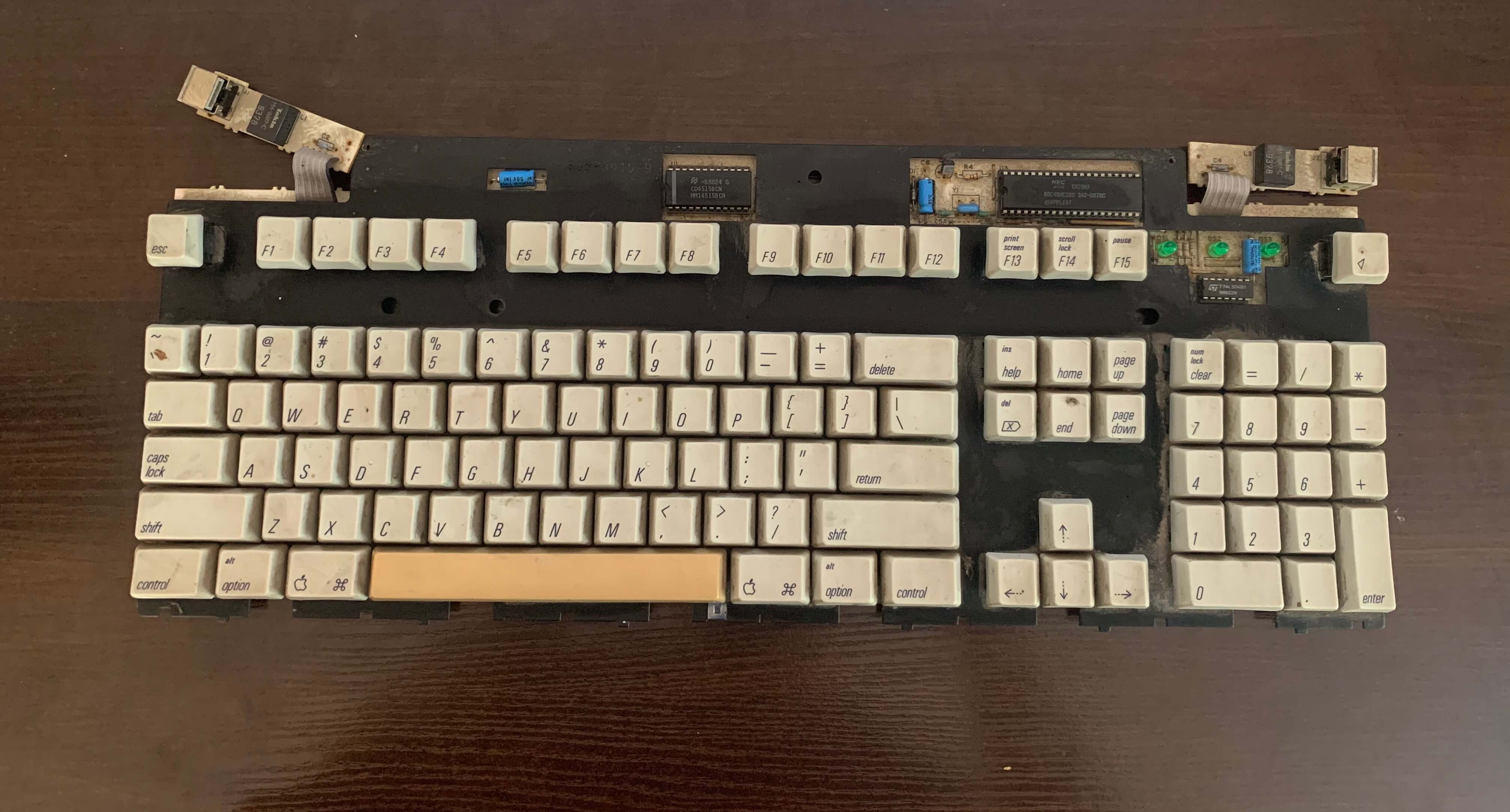
Then 20 years later, when the hype for mechanical keyboards is back, I’ve found the old M0115 in the basement of my parents’ house. Unfortunately without a case - just a board with keys. At the time I didn’t know what to do with it. A few days later accidentally I came around a blogpost describing an old apple keyboard conversion to a modern, 60% keyboard, using keycaps, switches, and metal plate under them. The author claimed the build preserves the original feel of the M0115 so I’ve decided to give it a try.
The most important part of the build, except for a donor M0115 would be a new board, with 60% layout and Atmega32u4 as a brain. You can order one from hasu based in Japan for around 50 bucks. Wait… 50 bucks? For a bit of laminate, diodes, and Atmega? We need to go cheaper! I’ve decided to make a board myself - I could also go with a hand-wired option, but I imagined wiring 60 switches and diodes together would be a nut job.
Ok, just to be clear - I’ve decided to do my own board as a hobby, not to save money. You will definitely not save money by wasting a lot of hours to redesign and produce PCB at home 😂 . 50$ is actually a good price as any PCB manufacturer will quote you a higher number. But still, I’ve decided to give it a try, just for fun.
The plan
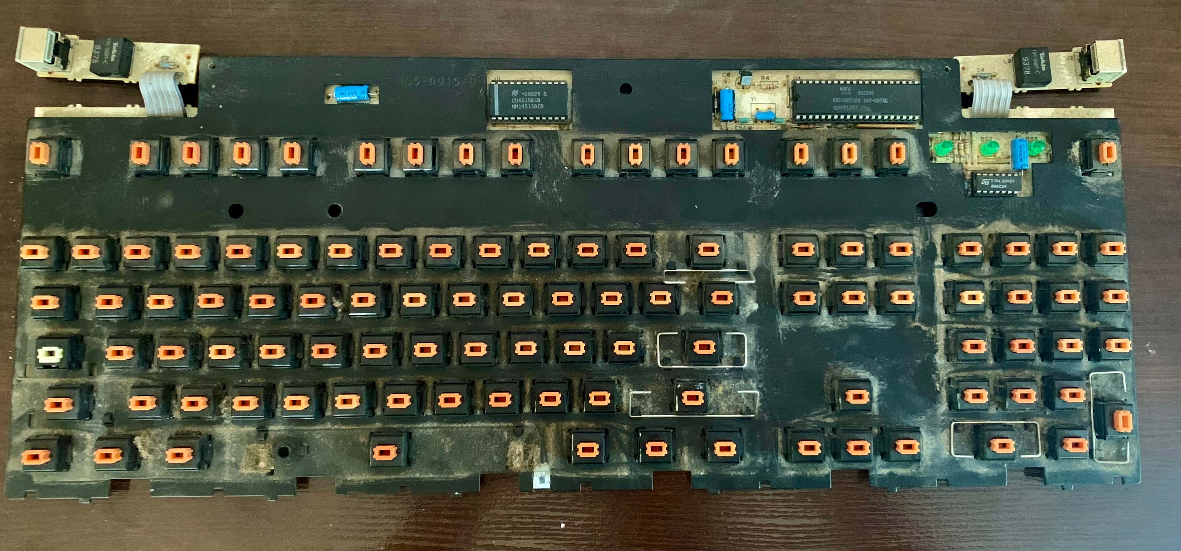
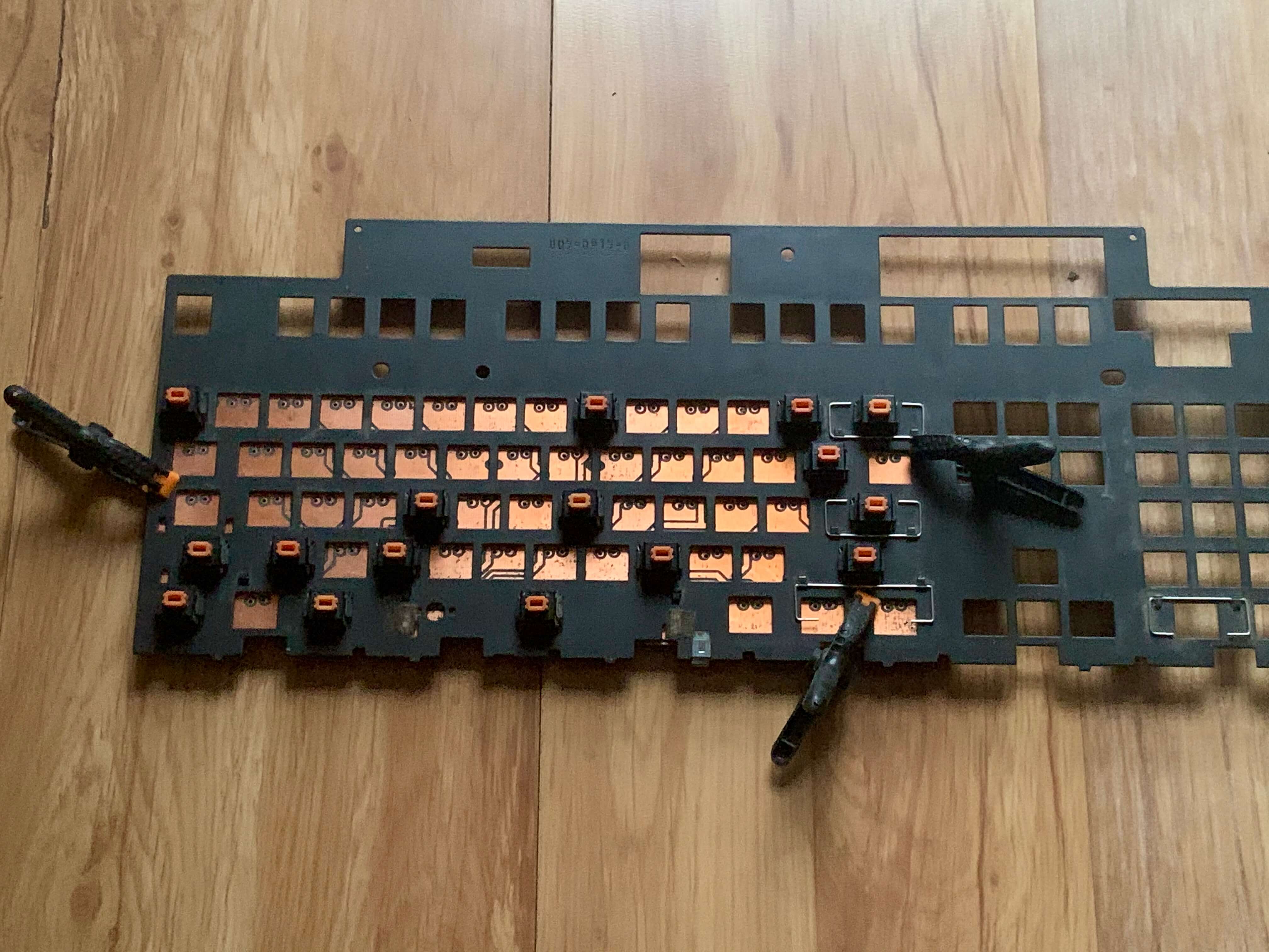
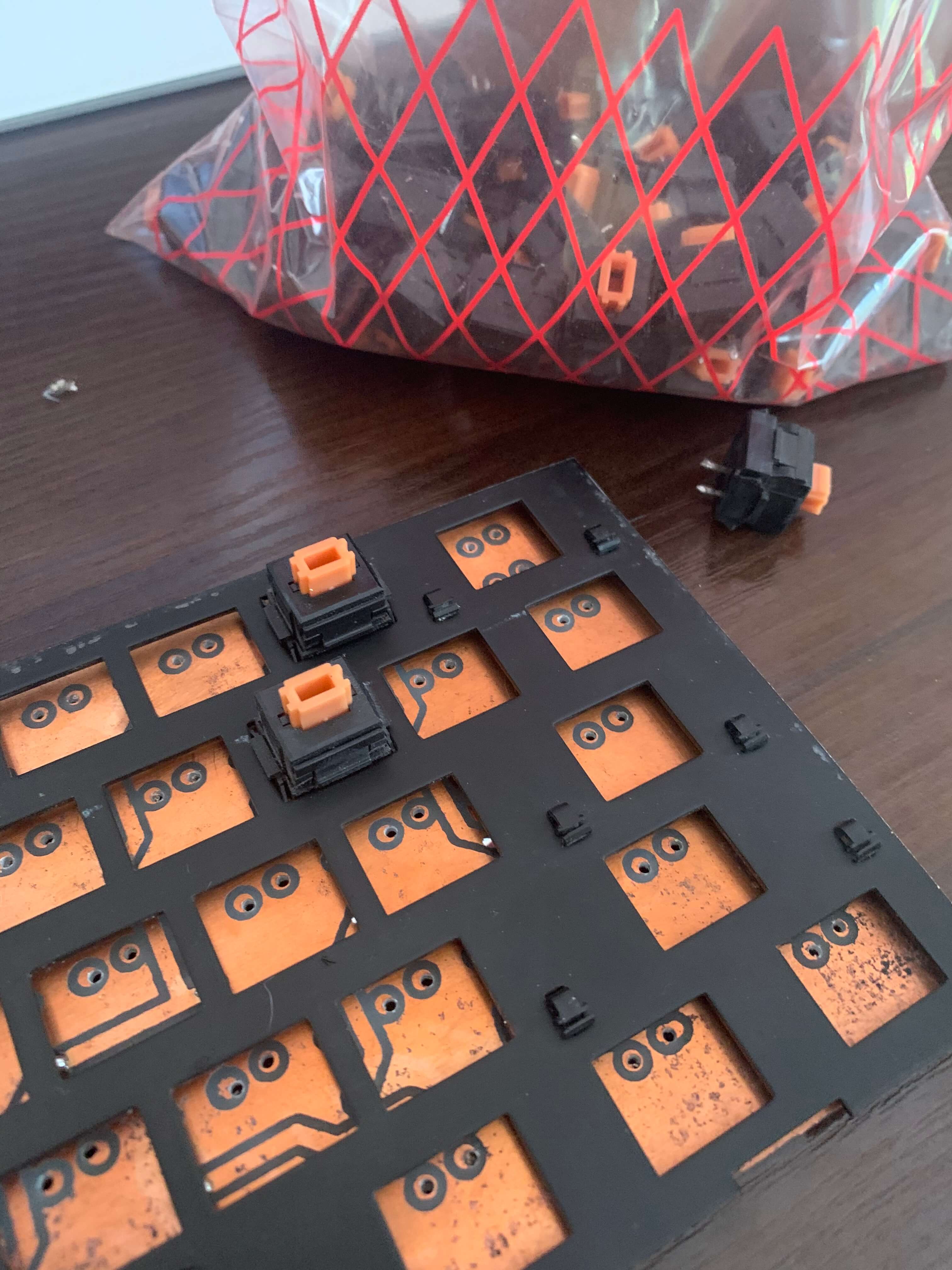
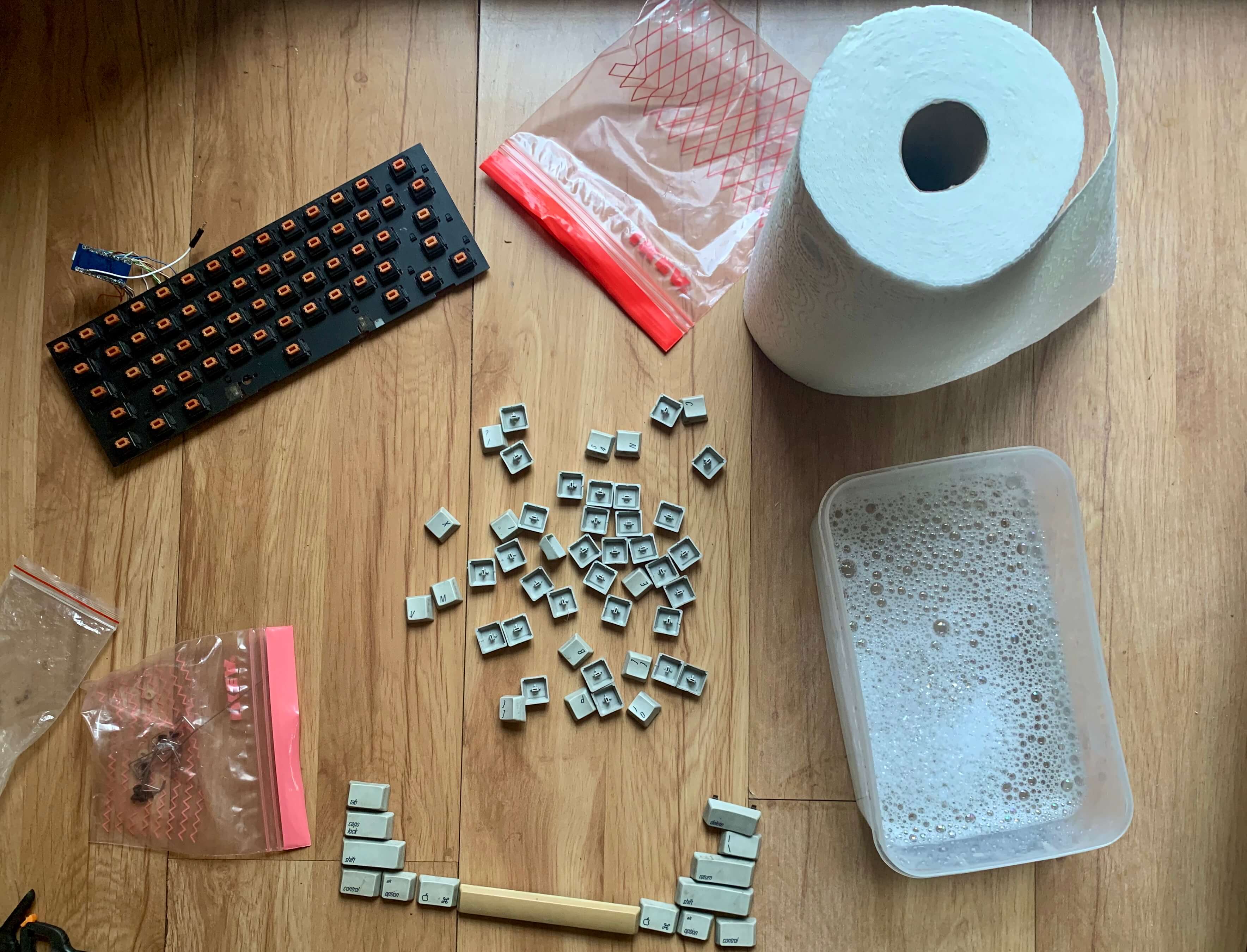
I’ve started with M0115 complete disassembly, including desoldering the switches. But that was easy-peasy.
When it comes to the build, the plan was to:
- Simplify board design to make it a little bit more tolerant for imperfections/misalignments. I’ll produce PCB at home which never is as precise as PCB manufacturers
- Use Arduino Pro Micro (it’s Atmega32u4 based) as a brain of operation - I’ll use Arduino instead of bare Atmega to avoid soldering small elements to my board, or rather small soldering points (which are also hard to create on homemade PCB unless you are a pro - I’m not). The microcontroller will be the same as in ready-made boards so the flashes will work.
- Use orange switches, metal board, and keycaps from the original Mxxx to preserve its unique look and feel
Bill of materials:
- M0115 Apple Extended Keyboard:
- ALPS orange switches
- Metal plate under the switches
- Arduino Pro Micro (with atmega32u4)
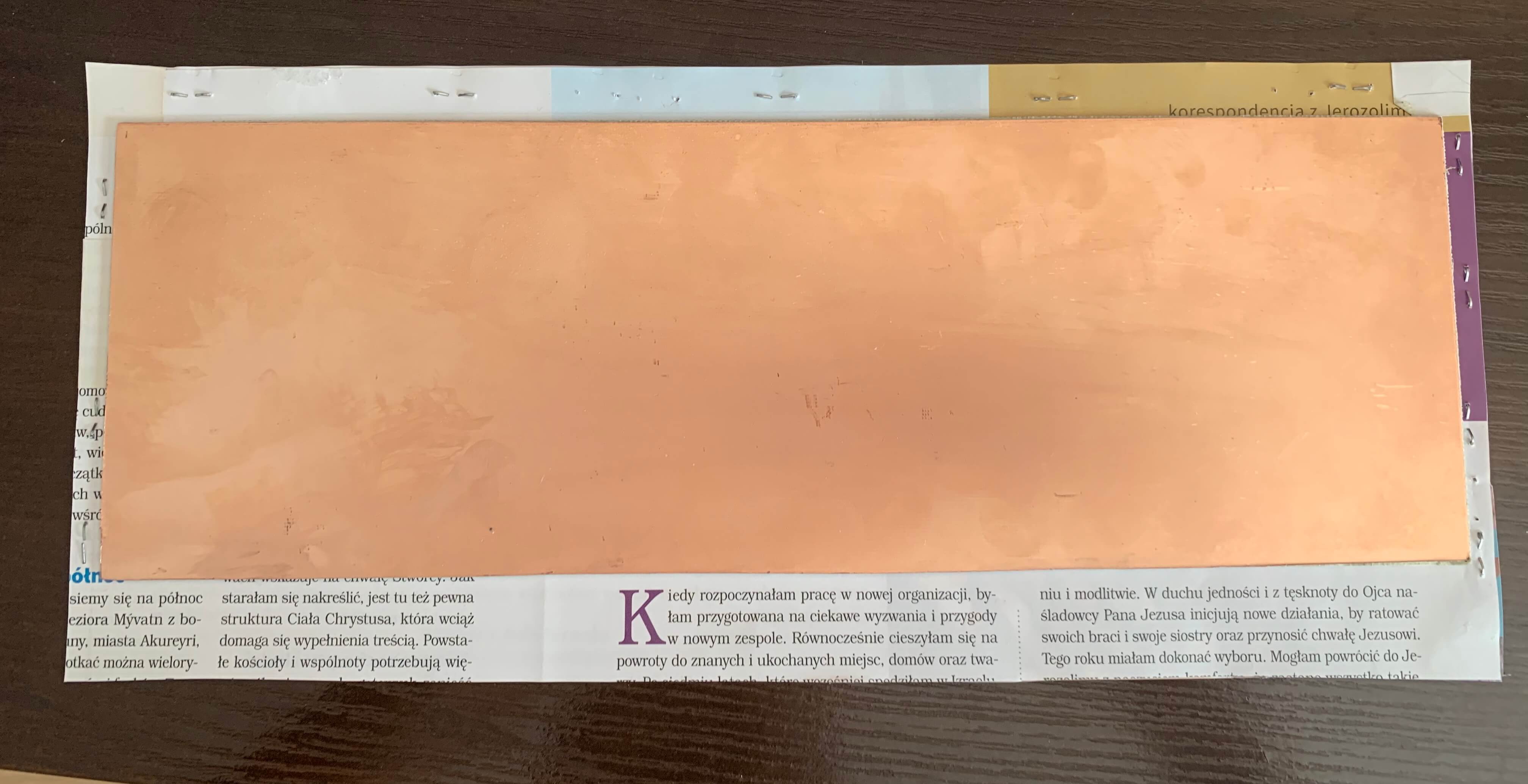
- Double-sided copper laminate for PCB (sized as the keyboard, I only found 14x31cm and had to cut it)
- 60 1N4148 diodes
- Few thick cables to connect Arduino to PCB and micro USB cable
Bill of tools:
- Soldering gear
- Regular household iron
- A drilling tool(preferably a cordless one)
- PCB drills 1,5mm and 0,7mm to drill the holes
- Sodium persulfate (Na2S2O8) to etch PCB, Acetone to clean it
- A LASER printer (A4 is enough fo 60% keyboard like this)
- Something to cut the keyboard metal plate
I had most of those things at home - hence only $10 in the headline.
Design
Hasu - the creator of TMK is kind enough to share the keyboard schematic and PCB design on GitHub (even better - its the whole Kicad project).
For me the problem with the original board design was that it was created with the assumption that it will be factory produced - it contained a lot of thick paths, the connection between layers, and optional solder joints. When making the PCB at home, increasing the number of elements, small joints, or thick paths, increases the risk of something going wrong.
I won’t go into details, but basically:
- I removed all components, paths, and pins which I won’t use - some of the joints for switches were multiplied as the original board is meant to be universal. I knew I will use it only with ALPS switches and AEK layout so I got rid of them.
- Removed all electronics which I had in Arduino
- Moved as many paths as I could to the bottom layer
- Created output pins for all columns and rows, which would be then connected to Arduino.
- Made sure that all through-layer connections are made with through-hole components (diodes in my case) as home-made boards do not have the connection between layers
- Made sure that switches are only connected on the bottom layer (as mentioned above no connection between layers and you cant solder on the front layer under the switch). And I thought - if I misalign the layers, I could still stick to the bottom and make a few jumpers to replicate the connection from the front layer.
- Made all solder points and paths as big as I could - thanks to that I gain some error tolerance when drilling the holes and aligning layers
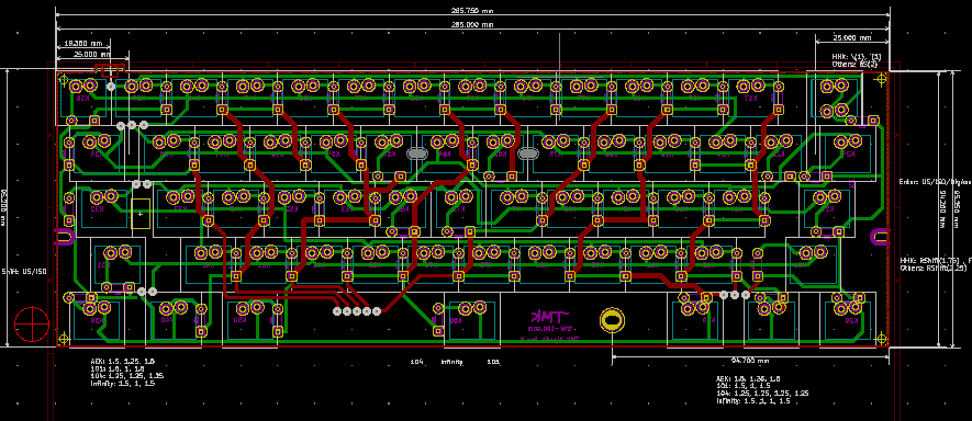
I didn’t use Kicad before but I’ve managed to get familiar with it shortly. You can see a final design (simplified alps64) HERE. Ok, we have the design, so its time to ship it to production!
Creating the PCB
Even though I successfully made some PCBs with my life, all of them were single sided. That means I didn’t have to worry about back and front layer alignment, and even if I misaligned the template it would still be ok. Unfortunately, my keyboard PCB was two-sided, so I had to find a way to align the layers perfectly while transferring the design to the copper plate.
For those not familiar how the PCB process looks like you can find an example here.
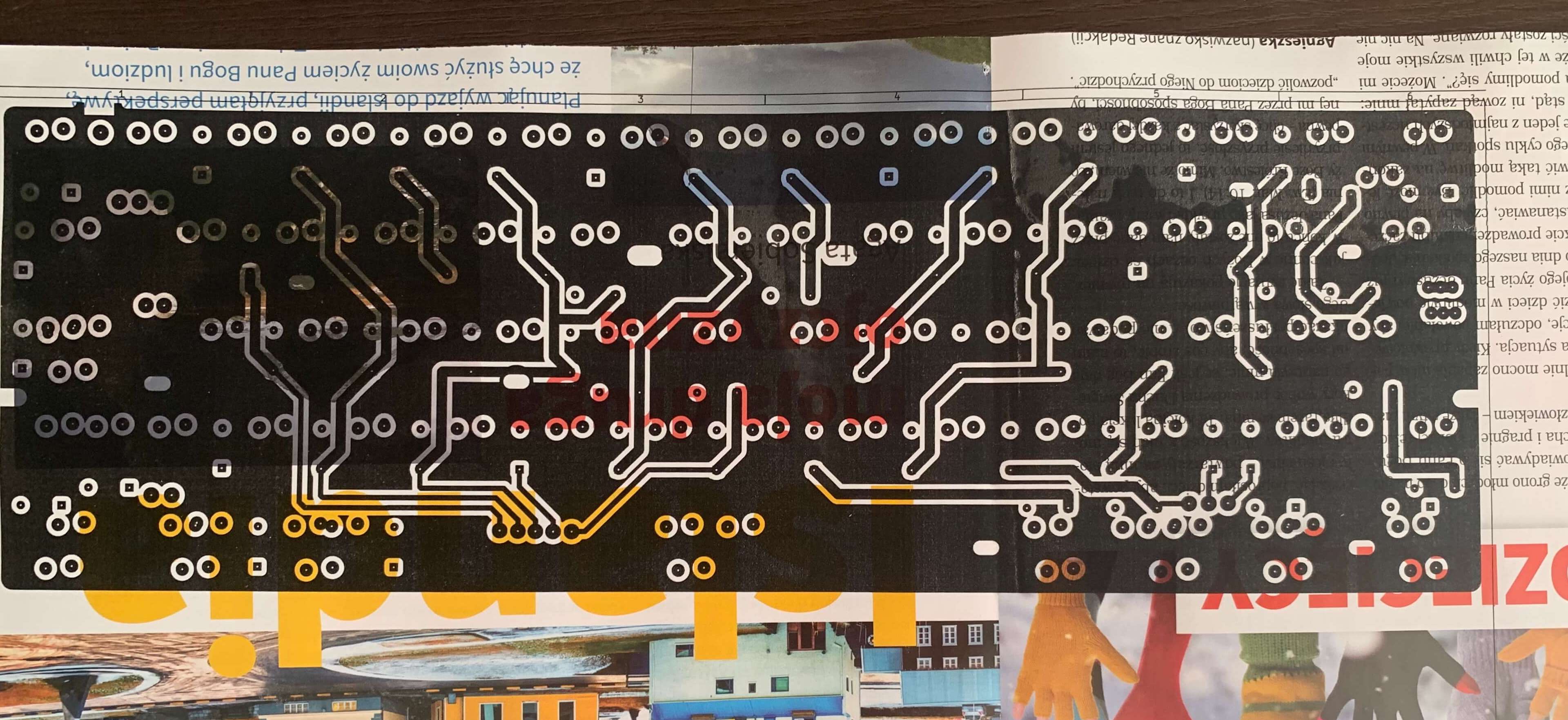
You need to buy laminate with a copper layer (on both sides in my case). Then cover the desired paths on it and chemically remove copper where it was not covered. You could mark the paths even using a regular Sharpie, but to make things easier and more precise I’ve decided to go with the thermo-transfer method - printed PCB design on a paper from an old magazine (the type of paper is important here) using a LASER printer and then used iron to transfer print to a clean and polished copper plate. The trick to make a two-layer design aligned is to create something like an envelope - join two sheets of papers with printed design on the inside, align them and then slide the board in - so it doesn’t move during the ironing process.
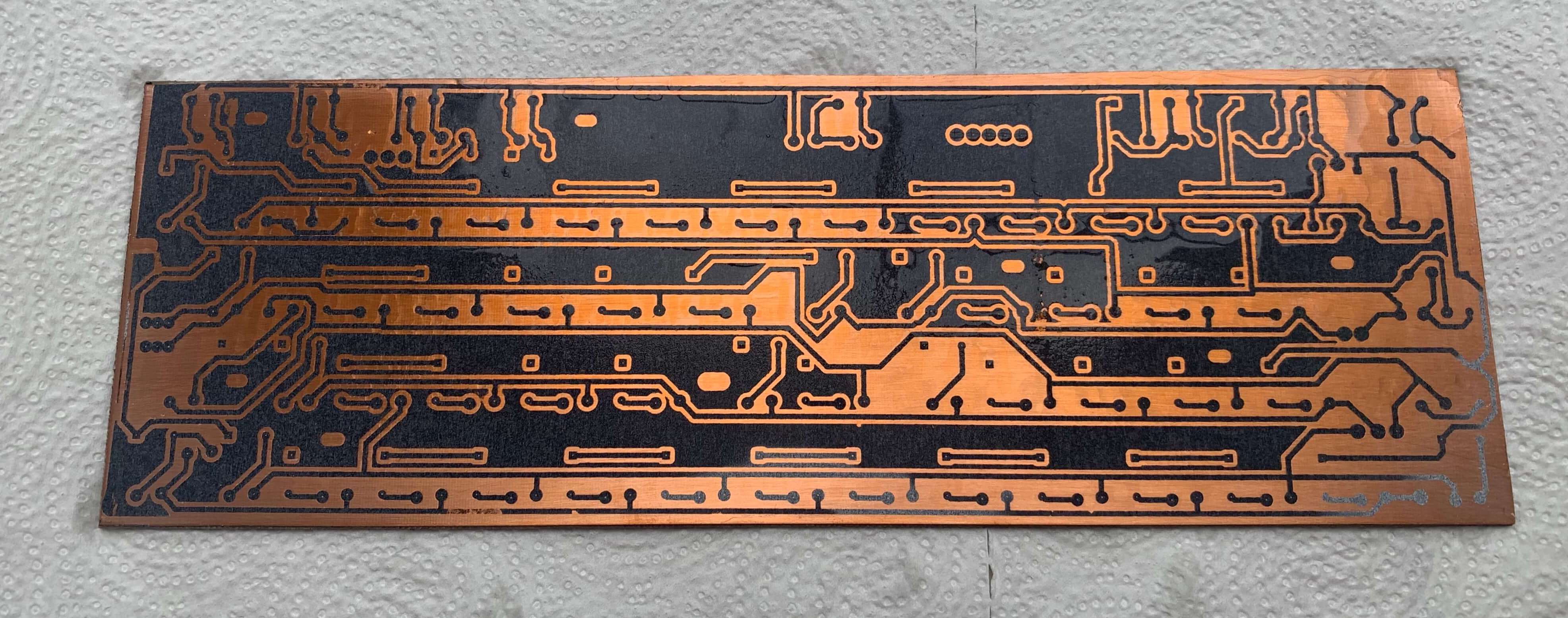
When my paths were marked on laminate I’ve put it into a sodium persulfate bath to remove the excessive copper. I didn’t have any device which would keep the proper temperature nor stir the fluid during the process so I had to wait about 2 hours for all the unmarked copper to be removed.
The last step of etching was to flush the board in water to get rid of sodium persulfate and remove leftover toner using acetone.
And it was ready! Wait… was it? I’ve tried to fit the metal plate and something seemed odd. THE BOARD WAS MIRRORED! Seriously, instead of mirroring the bottom layer while printing, I must’ve mirrored the front one. Layers fitted to each other but the design itself was mirrored.
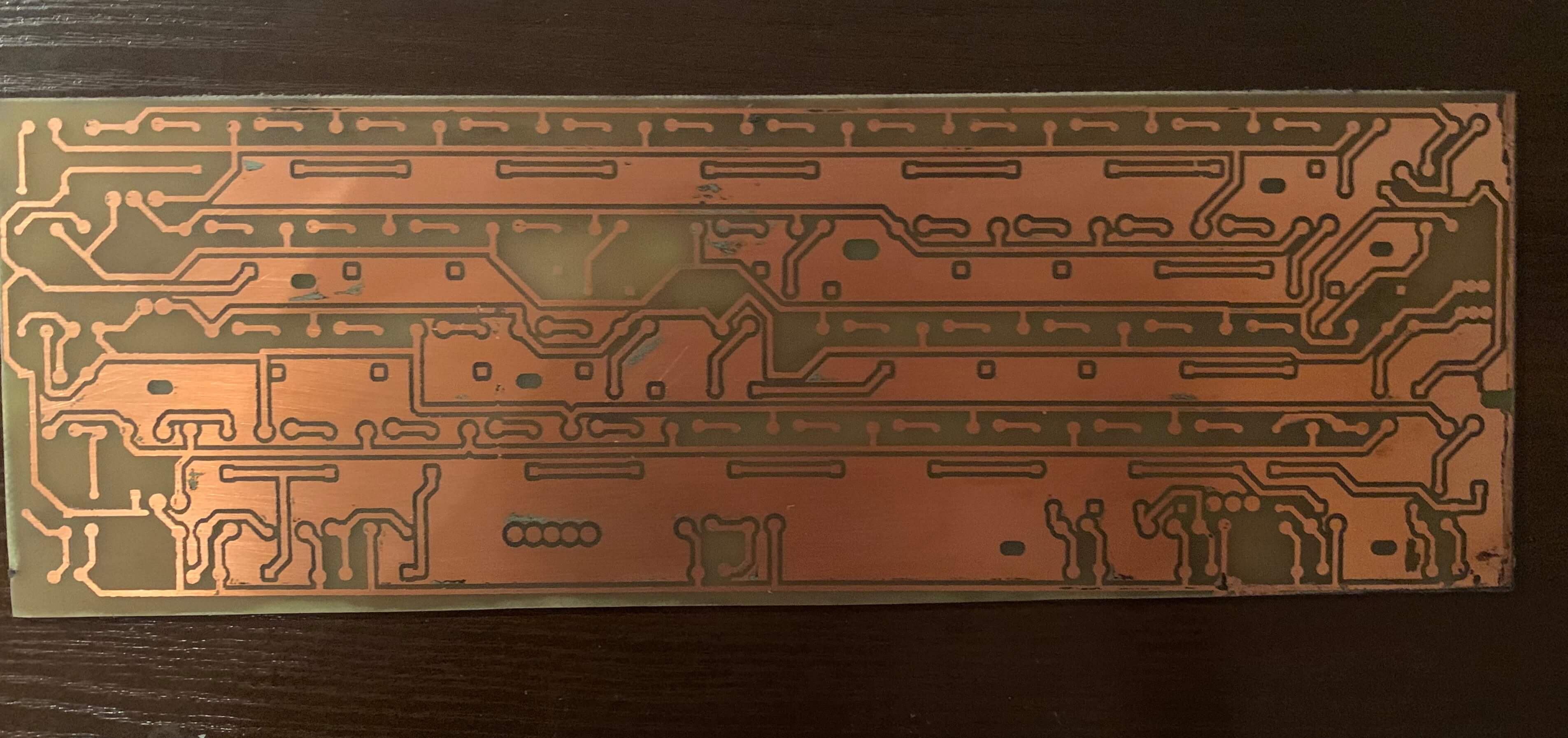
I didn’t want to have the enter key on the left, so I’ve started the whole process again. Thankfully I’ve thought about something going wrong at this step, so while ordering the laminate I ordered two identical boards. 2nd try was successful (maybe not that beautiful as the first one, but ok).
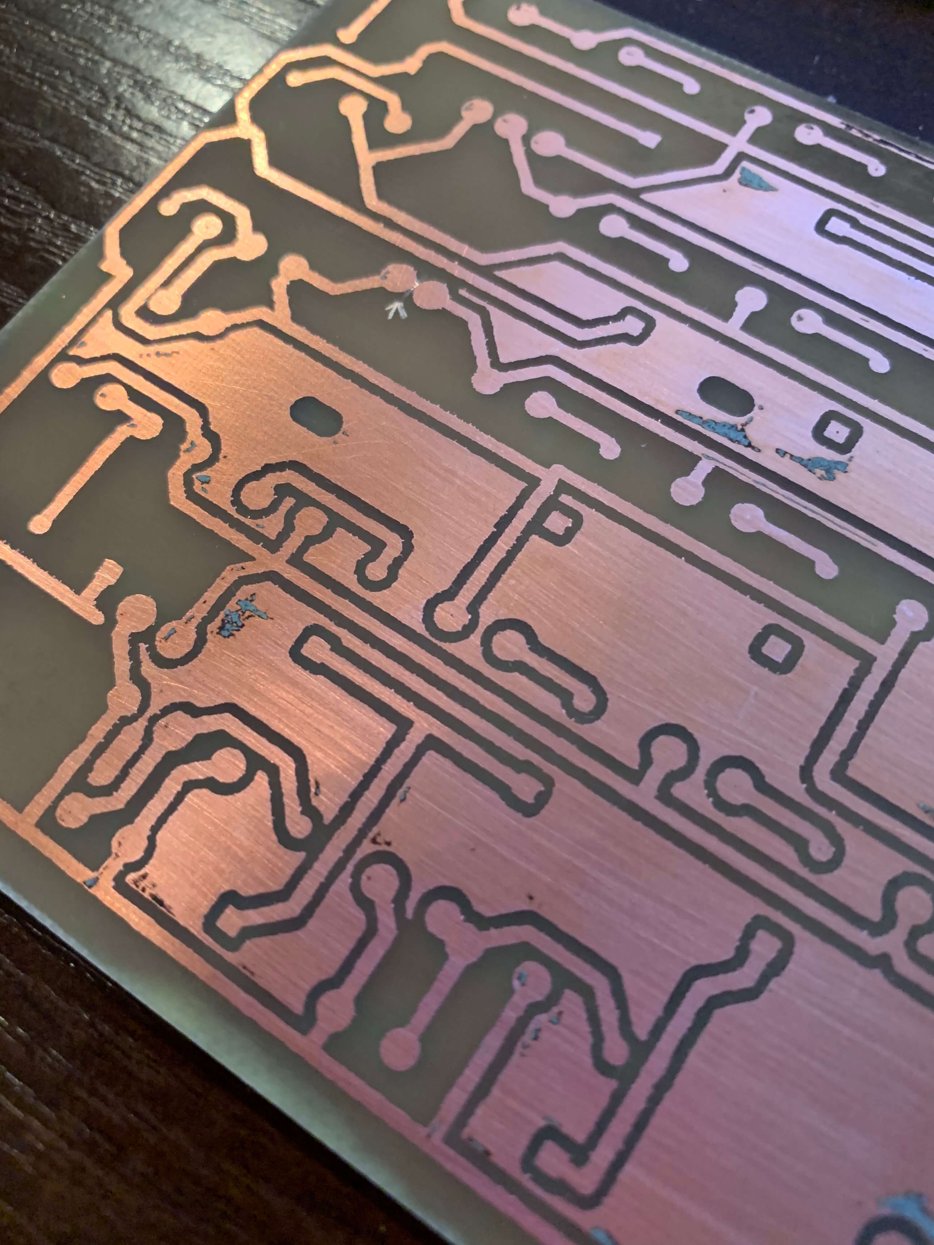
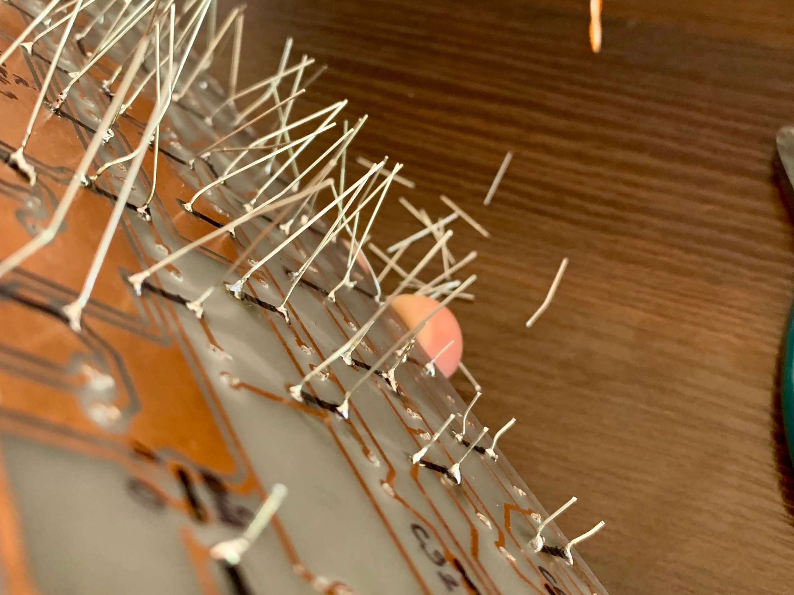
Last but not least I needed to drill holes - but this was rather simple. I’ve just used a 1.5mm and 0.7mm drill and a drilling tool. Fortunately, switches turned out to be quite tolerant for misaligned PCB holes - switch pin is flat and a little bit smaller than 1.5mm so almost all of them fitted perfectly.
Flashing the Arduino with hex file
To test the board I needed to flash the Arduino. it will detect keypresses on the keyboard and then send it to the computer. It has to be Pro Micro with atmega32u4 as it has a USB built-in, and can behave like a USB device.
To do this I had to load a proper program into Arduino. As I was heavily ‘inspired’ by hasu, I started with tmk_keyboard firmware created by him. My first thought was it should work after adjusting the pinout in the code (Arduino pro micro does not expose all of the Atmega ports on the board and also uses some for the Tx/Rx diodes).
Arduino Pro Micro pinout
The original TMK design uses a bare Atmega chip so it is able to utilize any pin it wants. I was limited to pins that Arduino exposes. If you look at the schematic, you can see which pins are exposed (source):
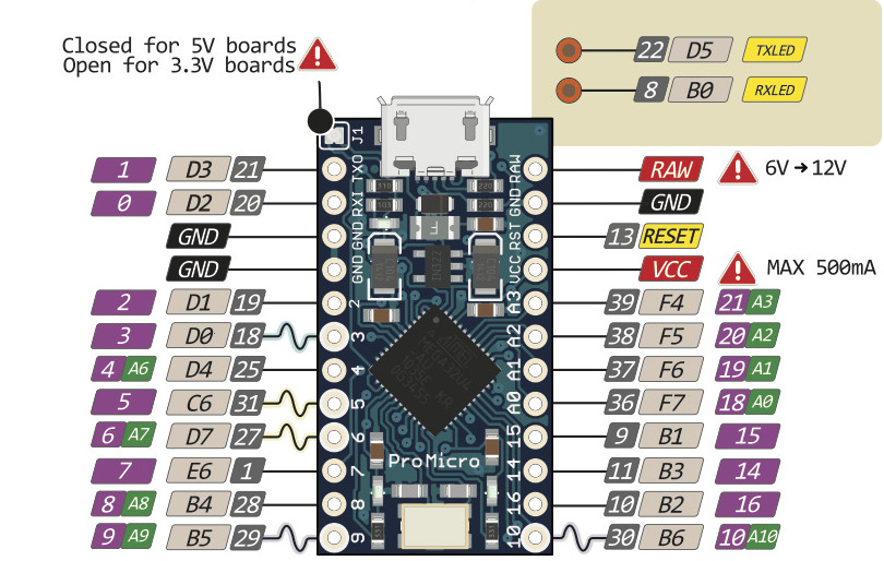
Thankfully analog pins could also work as digital ones (which I needed) so that was only a matter to remap the pins in firmware. Note: You can get 2 more pins if you desolder Tx/Rx diodes.
Modifying the firmware
TMK uses PORTB for columns, PORTD0-6, and PORTC2 for rows. In Arduino PORTD6, PORTC2 and PORTB7 are not available so all in all I just had to remap 3 pins. Looking at the sources, a keyboard firmware is built from 2 parts - tmk core library and a configuration for each layout (alps64 in my case). So in alps64, I’ve found a code responsible for pin mapping:
/* Column pin configuration
 * col: 0   1   2   3   4   5   6   7
 * pin: B0  B1  B2  B3  B4  B5  B6  B7
 */
static void  init_cols(void)
{
    // Input with pull-up(DDR:0, PORT:1)
    DDRB  &= ~0b11111111;
    PORTB |=  0b11111111;
}

/* Returns status of switches(1:on, 0:off) */
static matrix_row_t read_cols(void)
{
    // Invert because PIN indicates 'switch on' with low(0) and 'off' with high(1)
    return ~PINB;
}

/* Row pin configuration
 * row: 0   1   2   3   4   5   6   7
 * pin: D0  D1  D2  D3  D4  D5  D6  C2
 */
static void unselect_rows(void)
{
    // Hi-Z(DDR:0, PORT:0) to unselect
    DDRD  &= ~0b01111111;
    PORTD &= ~0b01111111;
    DDRC  &= ~0b00000100;
    PORTC &= ~0b00000100;
}

static void select_row(uint8_t row)
{
    // Output low(DDR:1, PORT:0) to select
    switch (row) {
        case 0:
            DDRD  |= (1<<0);
            PORTD &= ~(1<<0);
            break;
        case 1:
            DDRD  |= (1<<1);
            PORTD &= ~(1<<1);
            break;
        case 2:
            DDRD  |= (1<<2);
            PORTD &= ~(1<<2);
            break;
        case 3:
            DDRD  |= (1<<3);
            PORTD &= ~(1<<3);
            break;
        case 4:
            DDRD  |= (1<<4);
            PORTD &= ~(1<<4);
            break;
        case 5:
            DDRD  |= (1<<5);
            PORTD &= ~(1<<5);
            break;
        case 6:
            DDRD  |= (1<<6);
            PORTD &= ~(1<<6);
            break;
        case 7:
            DDRC  |= (1<<2);
            PORTC &= ~(1<<2);
            break;
    }
}
source: tmk_keyboard/keyboard/alps64/matrix.c
This was AFAIK the only part which needed changing. So i’ve altered the code to use pins i had available:
| ALPS64 Pin | Atmega Pin | Arduino Pin |
|---|---|---|
| ROW 6 | PD7 | 6 |
| ROW 7 | PC6 | 5 |
| COL 7 | PE6 | 7 |
I won’t dive into details how the pin configuration and state reading works (that would probably be enough for a separate article), I will just post the adjusted code to use the pins mentioned above:
/* Column pin configuration
 * col: 0   1   2   3   4   5   6   7
 * pin: B0  B1  B2  B3  B4  B5  B6  B7
 */
// Change col 7 from B7 to E6
static void  init_cols(void)
{
    // Input with pull-up(DDR:0, PORT:1)
    DDRB  &= ~0b01111111;
    PORTB |=  0b01111111;
    DDRE  &= ~(1<<6);
    PORTE |=  (1<<6);
}

/* Returns status of switches(1:on, 0:off) */
static matrix_row_t read_cols(void)
{
    return (PINB&(1<<0) ? 0 : (1<<0)) |
        (PINB&(1<<1) ? 0 : (1<<1)) |
        (PINB&(1<<2) ? 0 : (1<<2)) |
        (PINB&(1<<3) ? 0 : (1<<3)) |
        (PINB&(1<<4) ? 0 : (1<<4)) |
        (PINB&(1<<5) ? 0 : (1<<5)) |
        (PINB&(1<<6) ? 0 : (1<<6)) |
        (PINE&(1<<6) ? 0 : (1<<7));
    // Invert because PIN indicates 'switch on' with low(0) and 'off' with high(1)
    //return ~PINB;
}

/* Row pin configuration
 * row: 0   1   2   3   4   5   6   7
 * pin: D0  D1  D2  D3  D4  D5  D6  C2
 */
// changed:
// (row 6) D6 => D7
// (row 7) C2 => C6
static void unselect_rows(void)
{
    // Hi-Z(DDR:0, PORT:0) to unselect
    DDRD  &= ~0b10111111;
    PORTD &= ~0b10111111;
    DDRC  &= ~0b01000000;
    PORTC &= ~0b01000000;
}

static void select_row(uint8_t row)
{
    // Output low(DDR:1, PORT:0) to select
    switch (row) {
        case 0:
            DDRD  |= (1<<0);
            PORTD &= ~(1<<0);
            break;
        case 1:
            DDRD  |= (1<<1);
            PORTD &= ~(1<<1);
            break;
        case 2:
            DDRD  |= (1<<2);
            PORTD &= ~(1<<2);
            break;
        case 3:
            DDRD  |= (1<<3);
            PORTD &= ~(1<<3);
            break;
        case 4:
            DDRD  |= (1<<4);
            PORTD &= ~(1<<4);
            break;
        case 5:
            DDRD  |= (1<<5);
            PORTD &= ~(1<<5);
            break;
        case 6:
            DDRD  |= (1<<7);
            PORTD &= ~(1<<7);
            break;
        case 7:
            DDRC  |= (1<<6);
            PORTC &= ~(1<<6);
            break;
    }
}
TMK originally uses Atmega32u2 so I also changed the config file and set atmega32u4 as my uC. And then after installing dependencies and following the compilation guide from the tmk_keyboard repo I was able to create my own hex file. It’s time to flash!
Flashing Arduino Pro Micro
If you want to flash Arduino using Arduino IDE - it’s easy - just need to type in the code and click flash in the IDE. But it can get a bit complex if you want to upload a hex file by yourself.
Following the guide on tmk_keyboard GitHub, I knew I needed to use avr_dude to upload hex, and put Atmega in bootloader mode in advance. After some tries and failures, I found out that in order to do that you have to open a connection with 120bps for a moment, then close it and flash a device. I even found a handy script to do that for me - leonardoUploader.
So the process was:
- Short RST pin to GND twice, right after connecting the Arduino
- It should be visible in lsusb as Arduino SA or something similar.
- Run the script to open a 120bps connection for a moment
- Flash the hex file using AVR dude.
But even though the flashing process succeded, my device wasn’t detected. Whyyyyy?
# avrdude command used to flash:
/snap/arduino/41/hardware/tools/avr/bin/avrdude -patmega32u4 -C/snap/arduino/41/hardware/tools/avr/etc/avrdude.conf -cavr109 -F -D
# command used to run leonardoUploader:
./leonardoUploader /dev/ttyACM0 ~/Downloads/alps642.hex
Firmware alternative
As I didn’t feel like diving into C++ code and finding a reason why it doesn’t work (I have a keyboard waiting here!) I’ve decided to give another firmware a try - qmk_firmware. It was really tempting as I even found a GUI https://kbfirmware.com/ to configure keyboard and then download a hex file ready to upload to Atmega. And that was it! I just configured pinout using GUI and uploaded hex to Arduino just like I did before. The device was detected and I was able to write some chars by shorting pins on the Arduino board. At this time I was ready to test the board and even gained a user-friendly tool to create keyboard layouts in the future.
Btw. this shows that it was a good decision to modify the existing layout (alps64) instead of going for the custom one - it saved me time with creating a firmware, as in kbfirmware I could just select alps64 instead of defining key wiring by hand.
Testing the board
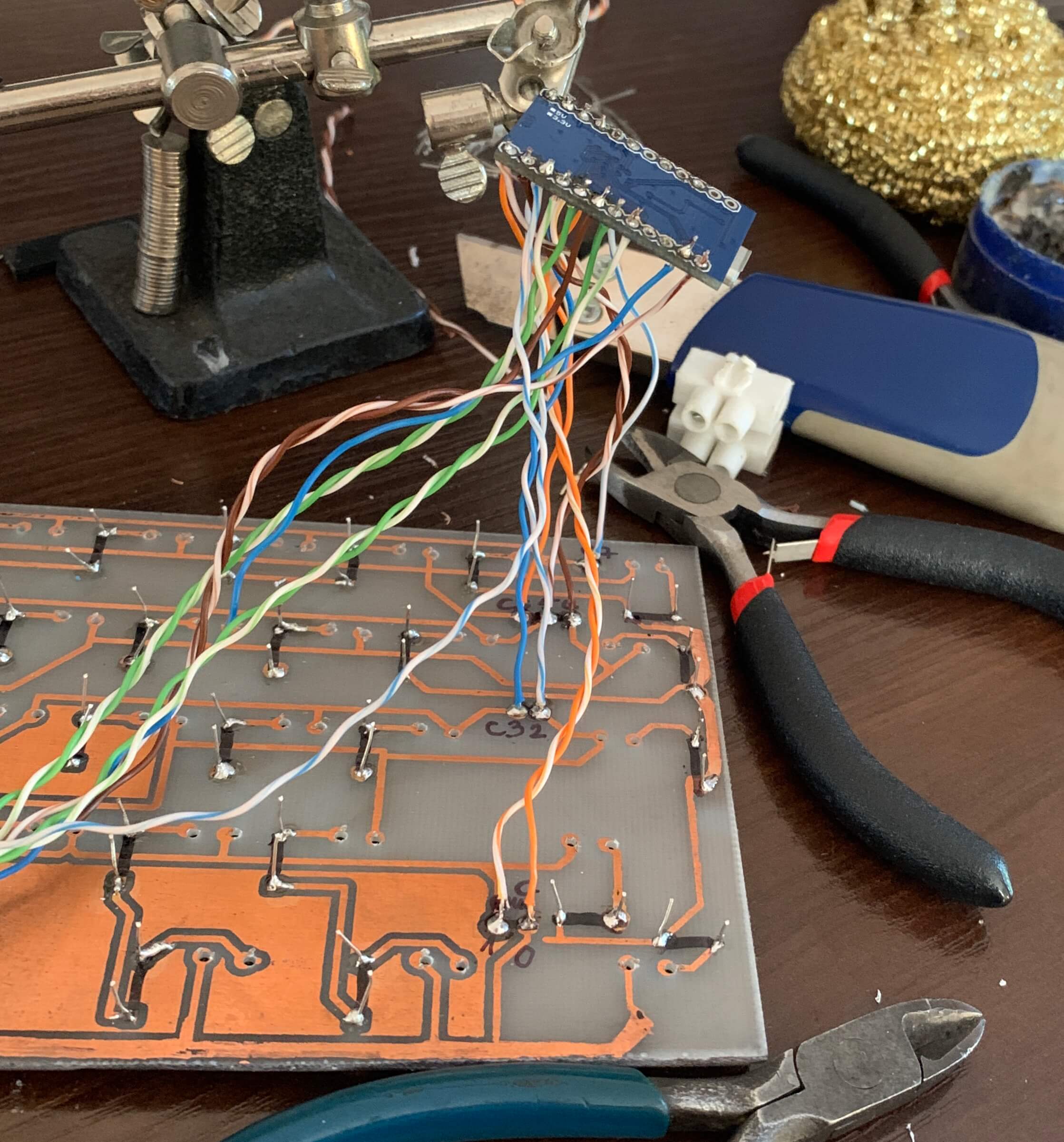
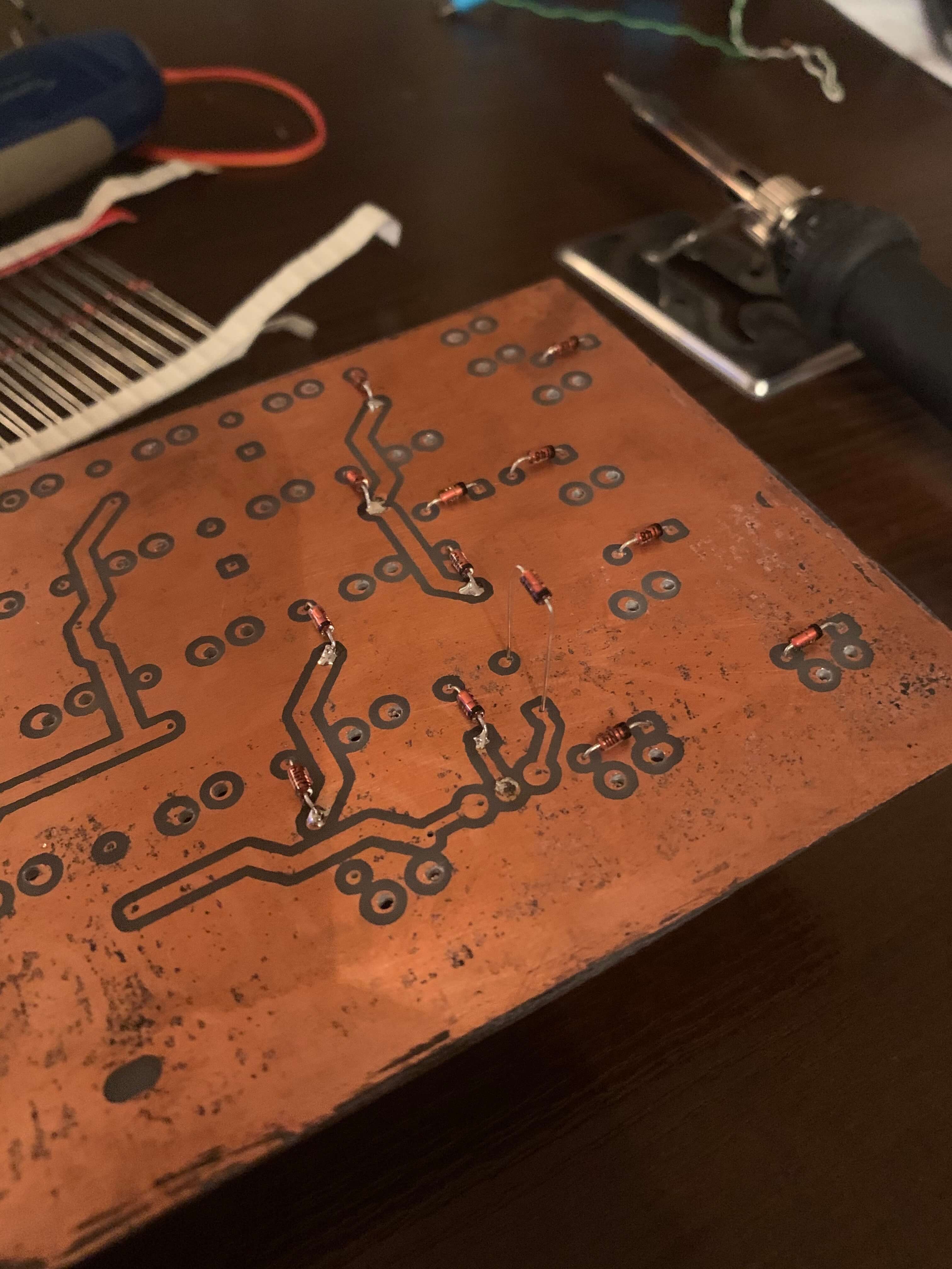
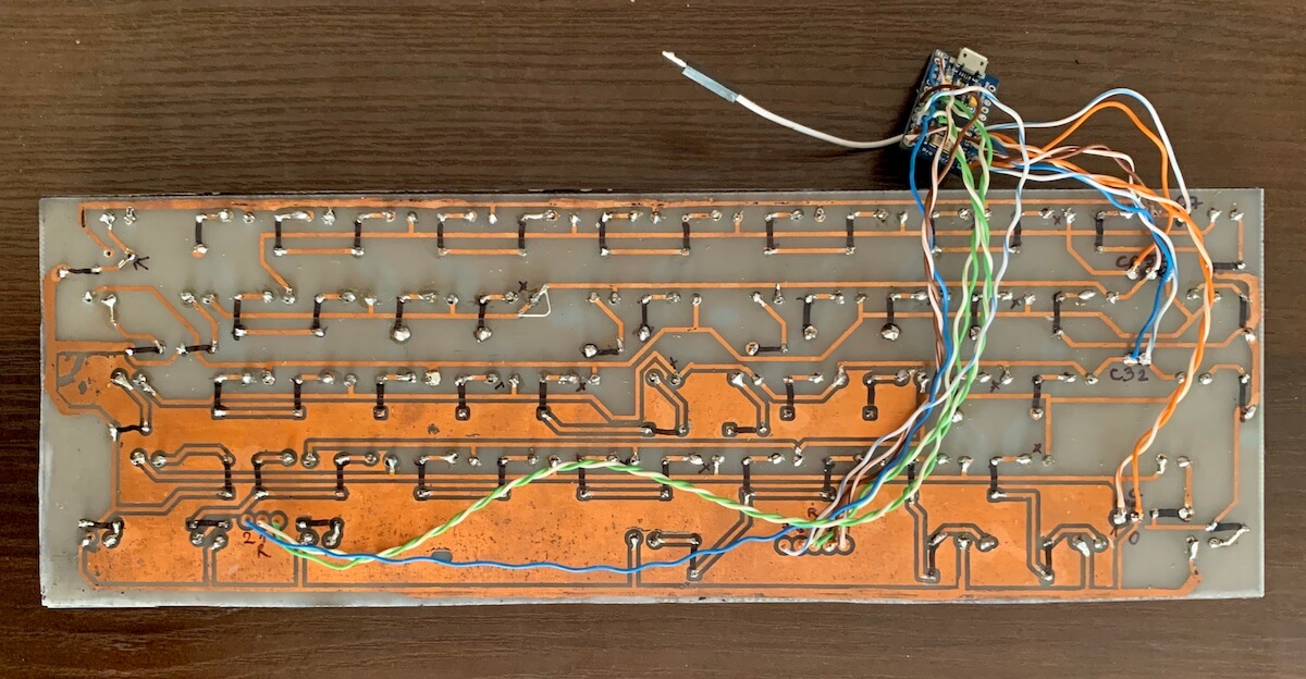
I’ve connected Arduino to my output pins according to the pinout I’ve set in the firmware. The test plan was to short switch soldering joints one by one to verify if key presses are recognized and therefore - the board works. But firstly I needed to solder all diodes in place - as I mentioned before, the connection between layers in my homemade board is made through diodes. Diodes are soldered on the top and bottom of the PCB, thanks to that, there is continuity between paths on both layers.
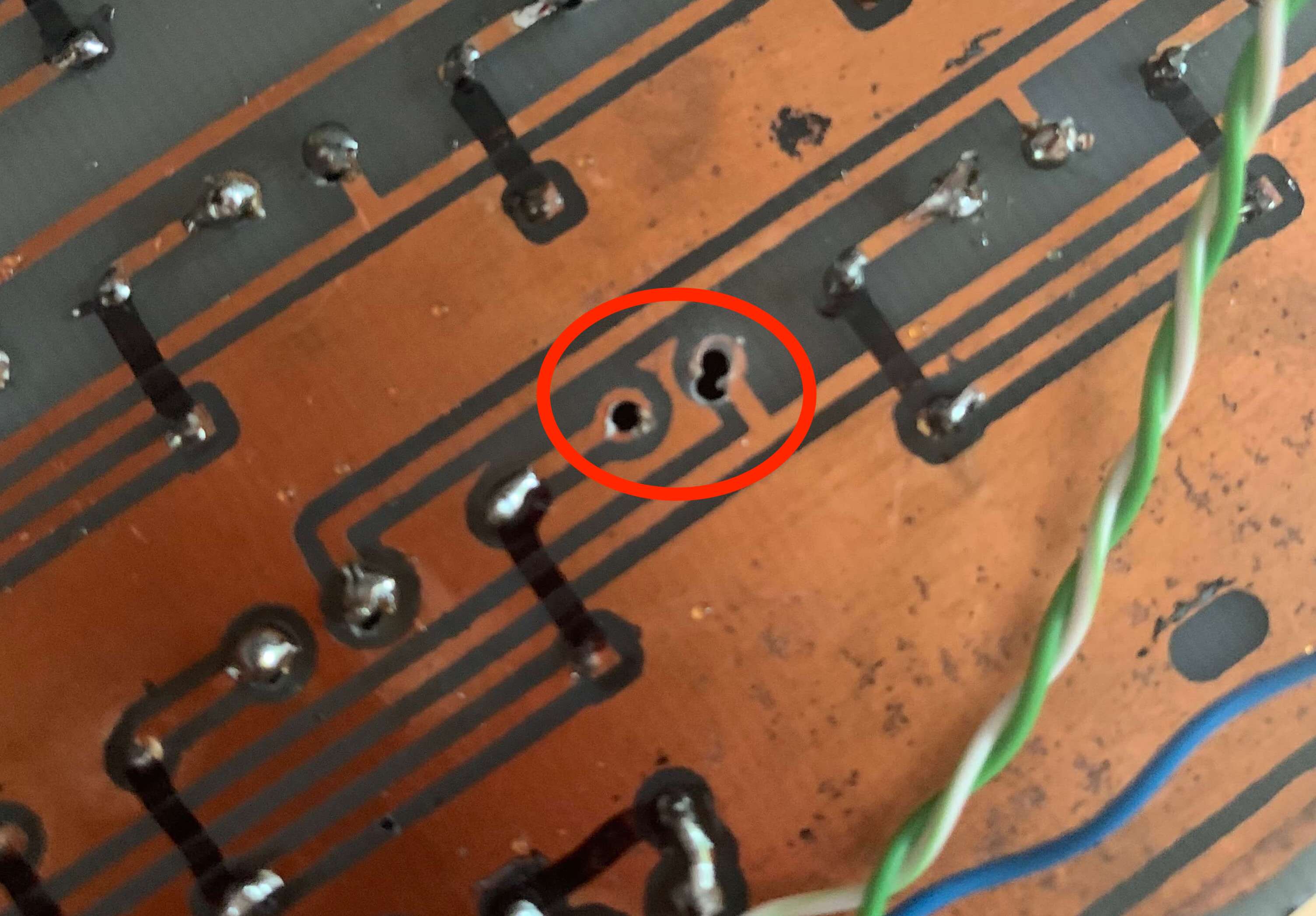
Then I’ve connected Arduino to USB, and having keyboardtester.com I started shorting joints one by one. Unfortunately, some keys were not working. It turned out that they shared one column and row. After some investigation and measurements, I’ve found out that two paths on my PCB were broken, even though they looked ok. But I’ve just put jumpers there (a bit of solder and a wire cut from the diode) and it was fixed. My board was officially working!
Assembly
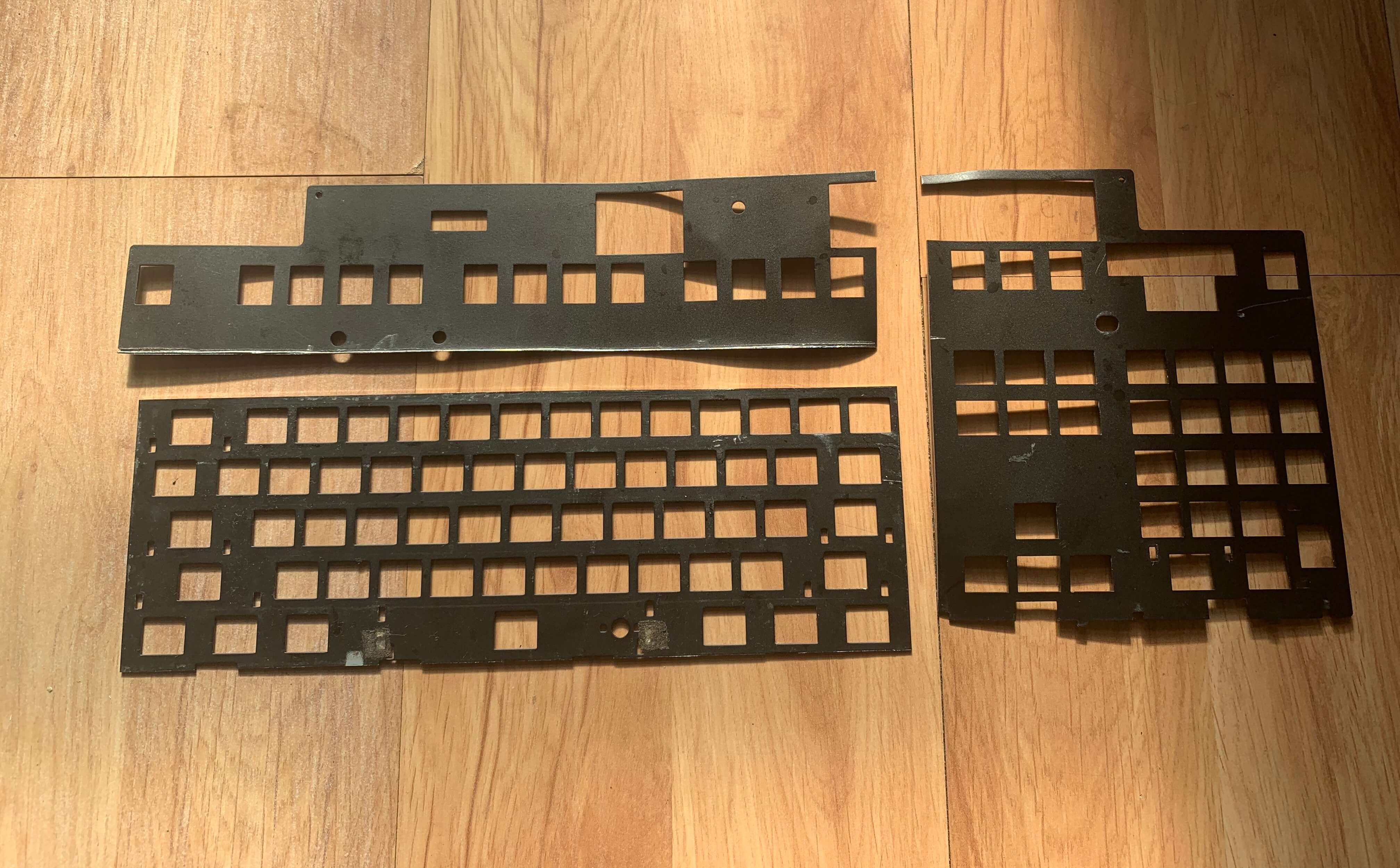
I wanted to preserve the original feel of M0115 so I kept the metal plate between switches and PCB. The original plate was a little bit bigger than my 60% keyboard so I needed to cut it first. I’ve started with marking the edges of the PCB on the plate just to know where to cut. Unfortunately, it turned out to be quite hard (its made from steel), at least with tools I had lying around. I took a shortcut there and took it to a local metal-things store, where they cut it for me on a machine for an equivalent of 2$. Easy peasy!
I had diodes already in place after testing so it was time for switches. But keep in mind that the metal plate goes between the PCB and switches (you kinda mount the metal plate first). You won’t be able to mount the plate after you’ve soldered the switches.
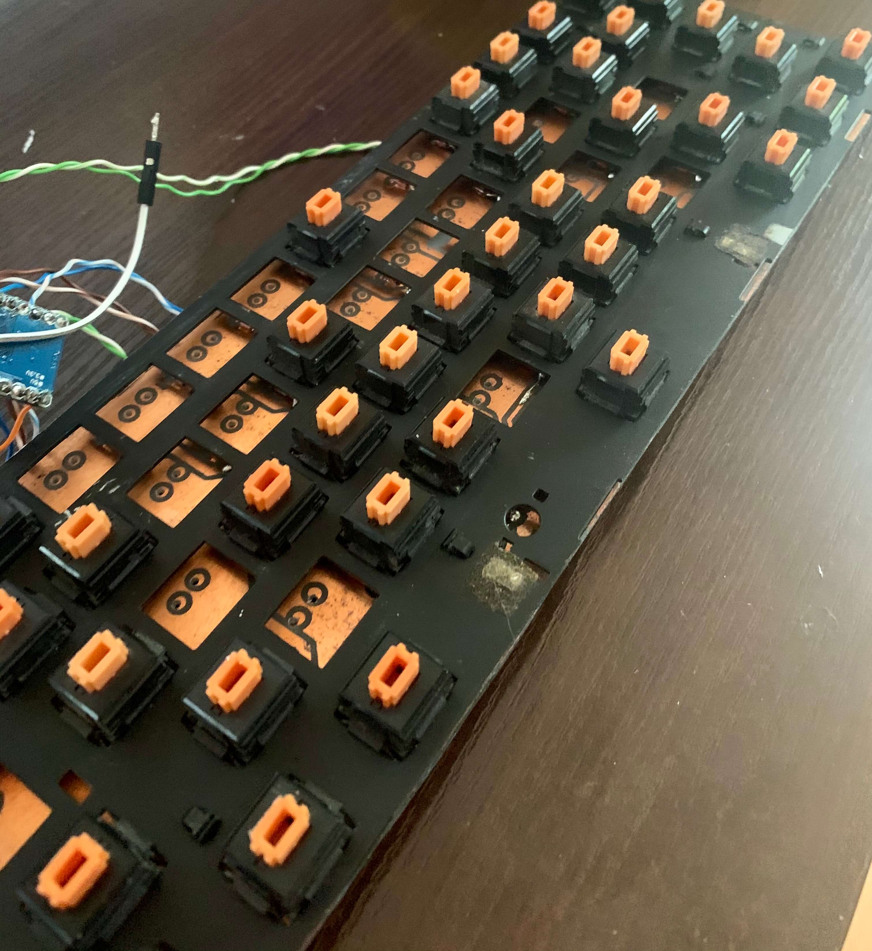
After fitting and soldering all the switches I’ve found out that I have to fix holes for 2 of them as they are misaligned too much. Fortunately, it was enough to just make other holes next to the existing ones.
After connecting the keyboard all keypresses were recognized correctly. Great success!
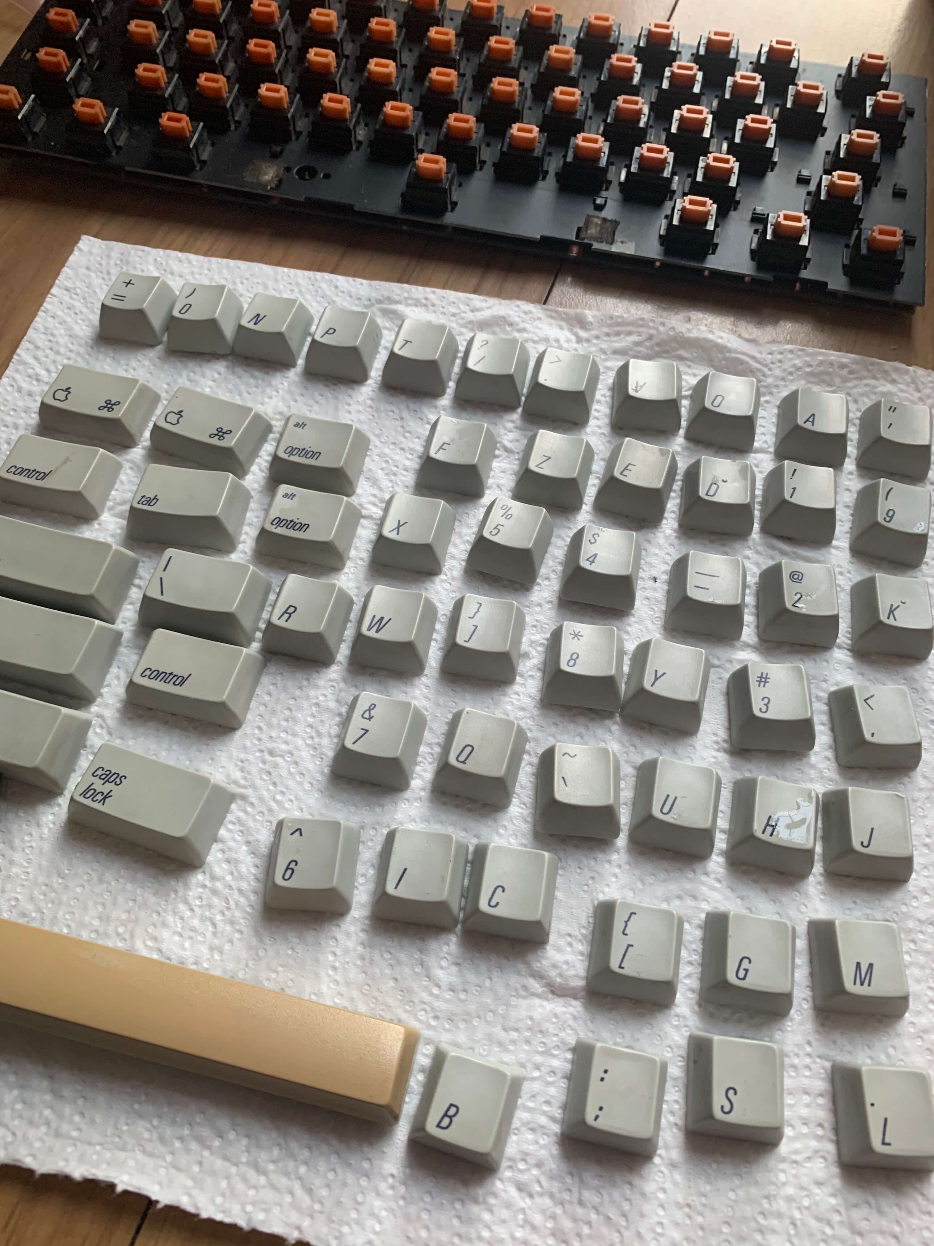
The only thing left was to clean the keycaps, as they were sitting in the dusty basement a few years. In order to do that, I put them into a warm bath with soap and cleaned each of them using a brush.
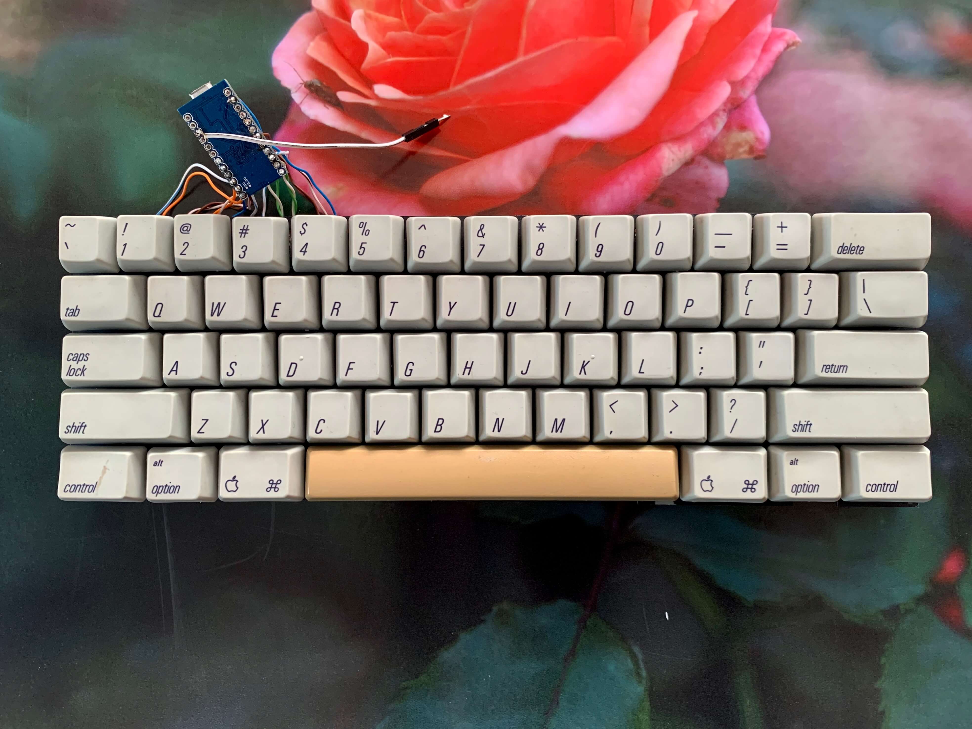
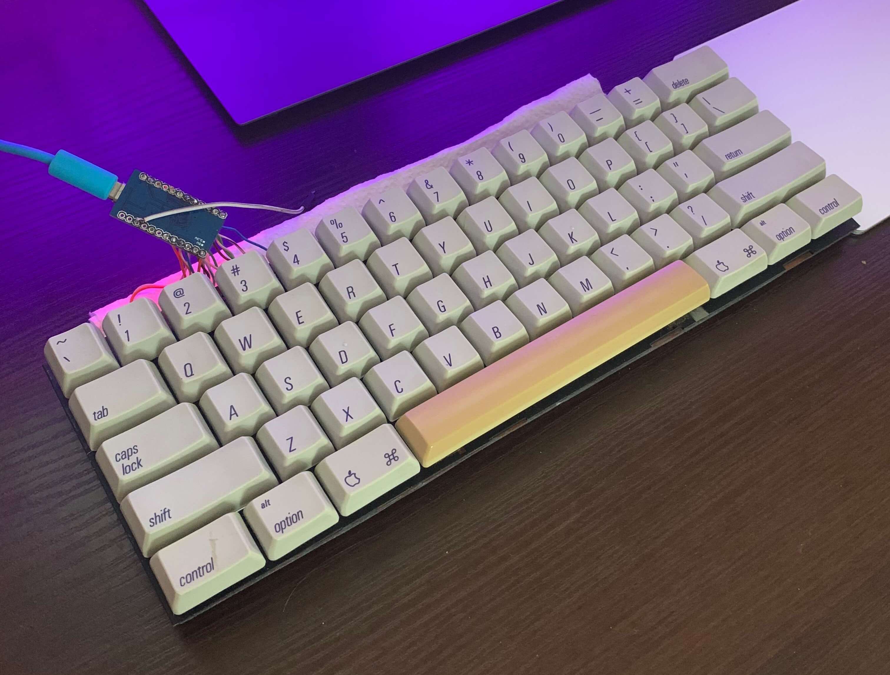
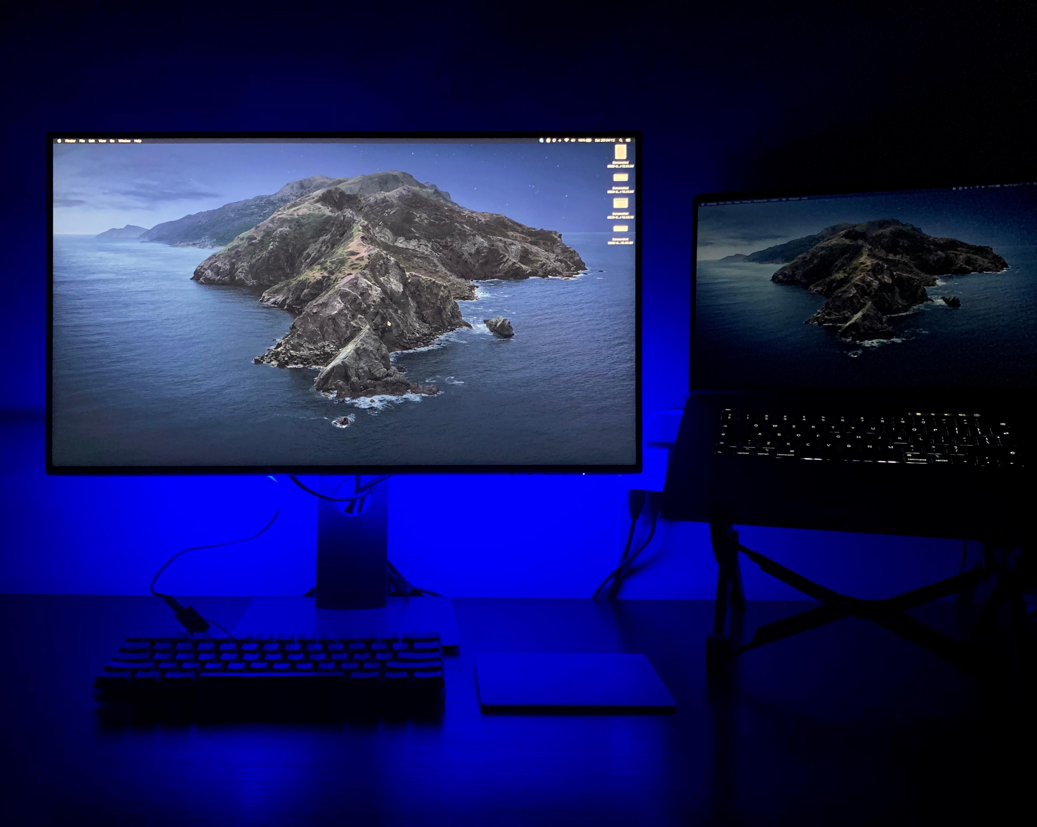
After making sure all keycaps are dry I mounted them on the switches. At this point, I was able to connect the keyboard and type this article (which was a pleasure). But the project didn’t end just yet!
Enclosure
I don’t have the enclosure yet. I plan to 3d print it, but as the projects, I’ve found on Thingiverse take around 14 hours and 120g of filament to print I need some time to think about the design (which will be slightly different as I have to fit the Arduino board somewhere).
Summary
It was quite fun to work on this project. At first, I wasn’t so sure I’d succeed. Now I have an awesome keyboard that cost me next to nothing and gained a great experience. It also includes the satisfaction that I’ve been able to turn something old and dirty into something cool and useful, all by myself!
When it comes to everyday usage - at first I was afraid that I will be missing arrow keys that don’t exist in a 60% layout, but it turned out that with the proper key mapping I don’t miss them at all. For now, I’m holding the right control as a modifier key and other keys behave as arrow keys. In VSCode I’m using a vim extension so I’m able to navigate between lines without arrows. The same goes for some function keys I heavily use on mac - like sound or playback control. I’m not missing a full layout anymore.
I probably won’t be bringing it into the office anytime as my coworkers would probably throw me away for that constant clacking noise the keyboard makes 😂
I have some ALPS switches left. What should I do with them?
References
- Blogpost about another AEK based build
- Geekhack thread with boards from hasu
- Alps64 Kicad project
- How to make pcb at home guide
- Arduino pro micro pinout
- tmk_keyboard firmware github
- leonardoUploader
- qmk_firmware github
- kbfirmware.com - qmk_firmware hex generator
- keyboardtester.com